 | 04 Sep 2018
Where to go from here? New cross layer techniques for LTE Turbo-Code decoding at high code rates
Stefan Weithoffer
Norbert Wehn
The wide range of code rates and code block sizes supported by todays wireless communication standards, together with the requirement for a throughput in the order of Gbps, necessitates sophisticated and highly parallel channel decoder architectures. Code rates specified in the LTE standard, which uses Turbo-Codes, range up to r=0.94 to maximize the information throughput by transmitting only a minimum amount of parity information, which negatively impacts the error correcting performance. This especially holds for highly parallel hardware architectures. Therefore, the error correcting performance must be traded-off against the degree of parallel processing.
State-of-the-art Turbo-Code decoder hardware architectures are optimized on code block level to alleviate this trade-off. In this paper, we follow a cross-layer approach by combining system level knowledge about the rate-matching and the transport block structure in LTE with the bit-level technique of on-the-fly CRC calculation. Thereby, our proposed Turbo-Code decoder hardware architecture achieves coding gains of 0.4–1.8 dB compared to state-of-the-art accross a wide range of code block sizes.
For the fully LTE compatible Turbo-Code decoder, we demonstrate a negligible hardware overhead and a resulting high area and energy efficiency and give post place and route synthesis numbers.


Our information society is increasingly being shaped by communication systems and this trend is accelerated by the evolution of mobile comminication systems. Today, the monthly data traffic per smartphone is expected to increase from 2.7 GB per month in 2016 to 18 GB per month in 2021 due to the widespread use of streaming video services, which creates more than 50 % of the annual mobile traffic increase as reported in the Ericsson Mobility Report (2016). To satisfy this hunger for higher data rates, sophisiticated wireless baseband signal processing is necessary. Here, we focus on the channel decoder, which is one of the most computationally intensive parts in baseband processing and thus a major source of latency and power comsumption.
Wireless communication standards like the 3GPP Long Term Evolution (LTE) use rate compatible Turbo-Codes as channel code. There, the transmit data rate (or code rate) R is adjusted dynamically to achieve a desired Signal-to-Noise-Ratio (SNR) while keeping the transmit power P constant and maximizing the information throughput (see Dahlman et al., 2010). For the LTE standards, including the newest release LTE-A Pro, code rates R up to r=0.94 and code block sizes K between 40 and 6144 bit are defined (see Third Generation Partnership Project, 2016). As a result, the channel decoder has to be extremely flexible with respect to code rates and code block sizes while achieving a very high throughput and a low decoding latency for large code block sizes. From the perspective of the decoder, flexibility means excellent decoding performance across a wide range of code rates and code block sizes. The high code rates are achieved by a rate-matching process, where a large part of the parity information and a small part of the systematic information of the code word, which is first encoded with a rate 1∕3 Turbo-Code, is disregarded and not transmitted. At the receiver side, LTE Turbo-Code decoders then work on the de-rate-matched received code word and same decoder hardware can be used for different code rates.
Highly parallel architectures as presented by Ilnseher et al. (2012), Wang et al. (2014), Shrestha and Paily (2014) or Belfanti et al. (2013), achieve LTE Turbo-Code throughput requirements. However, for the high degree of parallelism which is required to fulfill the throughput demands, the individual code blocks have to be split into (small) sub-blocks, which makes additional calculations to compute estimates for the state metrics at the sub-block borders necessary in order to mitigate a degradation of the decoding performance in terms of Frame Error Rate (FER). This, in turn, limits the maximum degree of decoder parallelism that can be achieved for a given target FER. Moreover, this effect is even more pronounced for high code rates, which are mandatory to increase the information throughput. In Summary, the flexibility of todays communication standards with respect to code rates and code block sizes requires a special consideration of high code rates for the architecture design.
Contributions and outline
In this paper, we follow a cross-layer approach to increase the FER performance for a fully LTE-A Pro compatible Turbo-Code decoder hardware architecture without the need to trade off throughput against FER performance. We employ a combination of new techniques developed in our group and use synergies accross different layers of the decoding to improve the FER performance significantly accross a wide range of code block sizes and code rates. Starting from a fully LTE-A Pro Turbo-Code decoder architecture optimized for high throughput, we demonstrate the negligible hardware overhead of the improved algorithms. To the best of our knowledge, a most advanced hardware implementation of a complete Turbo-Code decoder with the new techniques, which enable coding gains up to 1.8 dB compared to state-of the-art with negligible overhead, is demonstrated for the first time. The rest of this paper is structured as follows: Sect. 2 will give background information on state-of-the-art Turbo-Code decoder architectures and the LTE Turbo-Coding scheme. Section 3 then describes our Cross-Layer approach and the employed techniques before Sect. 4 discusses the proposed Turbo-Code decoder architecture with a focus on the architectural changes for the implemented techniques compared to state-of-the-art.
Post place and route implementation results will be discussed in Sects. 5 and 6 concludes the paper.
A Turbo-Code decoder consists of two component decoders that process the received code word in an iterative loop (see Fig. 1a). First the component decoder 1 processes the data in the original order and passes so called extrinsic information Λ to component decoder 2. Then, component decoder 2 works on the permuted (interleaved) input data and extrinsic information. The extrinsic information generated by component decoder 2 is then passed to component decoder 1 for the next iteration of the loop. Each run of one component decoder is counted as one half-iteration (HI). In practical implementations, one decoder, implementing the max-Log-Map algorithm (see Robertson et al., 1995), functions alternately as component decoder 1 and component decoder 2. The decoding continues until either a maximum number of HIs has been reached, or until a stopping criterion is fulfilled.
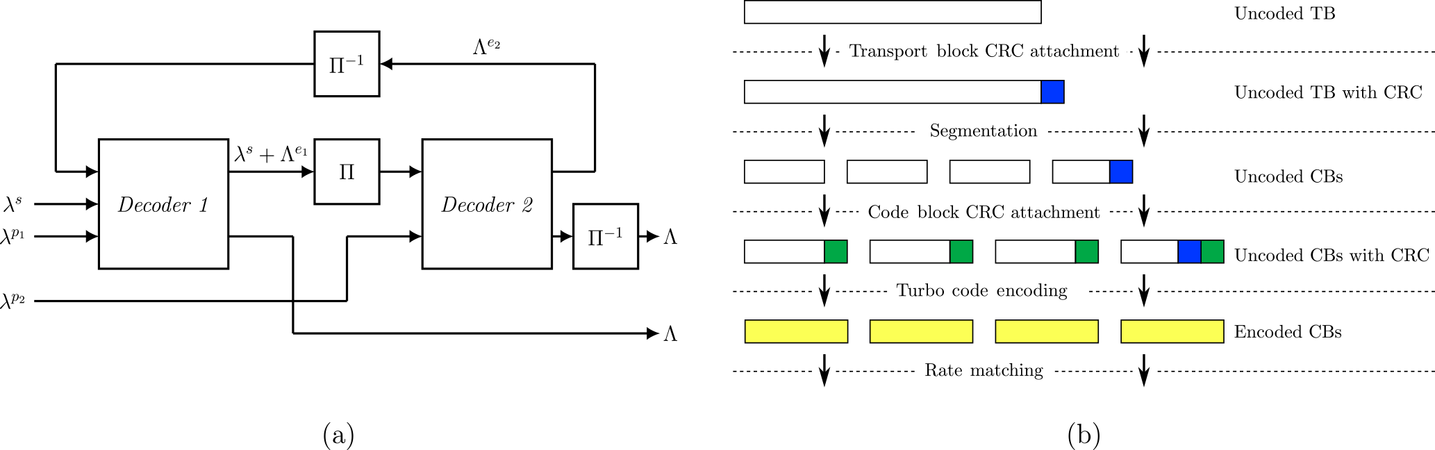
Figure 1(a) General Turbo-Code decoder with CRC. Π: Interleaver. Π−1: De-interleaver; (b) LTE-A channel coding scheme for DL-SCH
2.1 High throughput turbo-decoder hardware architectures
State-of-the-art Turbo-Code decoder hardware architectures can be classified based on their approach on how to parallelize the inherrently serial max-Log-Map algorithm:
Parallel Map. (PMAP) – decoders use spacial parallelism by splitting the code block trellis into sub-trellises (or sub-blocks) that are decoded on p parallel sub-decoder cores (see Fig. 2a) and parallel windowed processing of forward and backward recursions within the cores. Implementations which use the PMAP architecture are reported, for example by Belfanti et al. (2013), Sun and Cavallaro (2010), Ilnseher et al. (2012) and Shrestha and Paily (2014).
Fully Pipelined Map. (FPMAP) – decoders implement a fully parallel processing of both component codes Li et al. (2016b), Li et al. (2016a) (see Fig. 2b). The recently published architecture promises very high throughput and can be seen as an extreme case of the PMAP architecture where each sub-trellis essentially consists of one step of the original trellis.
Pipelined Map. (XMAP) – decoders, as reported by Ilnseher et al. (2010) or Wang et al. (2014), unroll and pipeline the recursions, a functional parallelization. Each clock cycle, one continuous sub-trellis (window) is fed into the “X”-shaped pipeline structure (see Fig. 2c) which gives the decoder its name.
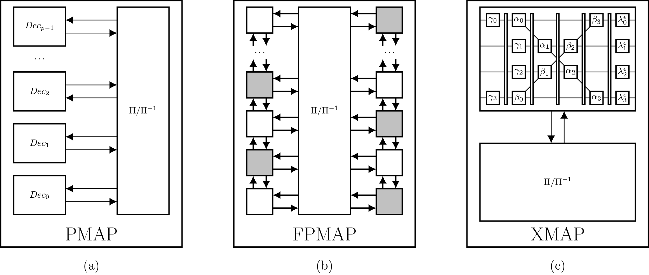
Figure 2Decoding of a code word of size K on a: (a) PMAP decoder with p sub-decoder cores, (b) FPMAP decoder, (c) XMAP decoder with p pipeline stages; : Interleaver/Deinterleaver.
Spliting up the code block trellis into sub-blocks or windows, however, weakens the protection of the bits at the sub-block/window borders, because state metric information is lost. Since the FPMAP architecture leads to sub-trellises consisting of only one step, this effect is more pronounced for the FPMAP and is the reason why it needs more iterations than the other decoder types, even at rate 1∕3. For the other decoder types, the state metrics at the sub-block borders can to be estimated.
The estimation for the state metrics at the sub-block borders can be taken from a warm-up recursion phase (acquisition – ACQ) or from the state metric calculations of the previous iteration (Next Iteration Initialization – NII) as proposed by Dielissen and Huiskens (2000). For very small windows and/or high code rates, a combination of ACQ and NII can be used to mitigate very long acquisition lengths (see Roth et al., 2014). Note, that state-of-the-art Turbo-Code decoders expect their input depunctured to rate 1∕3 and thus do not take into account the puncturing pattern that is used to adapt the rate.
For small code block sizes K and large degrees of parallelism p, the sub-block sizes become very small. Thus, the achievable level of parallelism for a desired Quality of Service (QoS) is limited, especially for high code rates. Therefore, in state-of-the-art PMAP decoders, smaller code words are only decoded on a fraction of the available sub-decoder cores and the smallest code block sizes (i.e. ) are decoded only using a single sub-decoder core while the others remain idle.
2.2 LTE-A turbo coding for DL-SCH
The LTE standard organizes the data to be transmitted over the Downlink Shared Channel (DL-SCH) in each transmission time interval (TTI) in transport blocks (TB) which have sizes ranging from 16 to 97 896 bit (see Third Generation Partnership Project, 2016). The DL-SCH channel coding scheme is depicted in Fig. 1b. The uncoded transport block is first attached with a 24 bit CRC for the hybrid automatic repeat request (HARQ) protocol. Then, the transport block is divided into smaller code blocks if its size (with attached CRC) is larger than 6144 bit. This process is called code block segmentation. After segmentation, the code blocks contain a maximum of 6120 bits and are each attached with another 24 bit CRC (the code block CRC) before being encoded with a rate 1∕3 Turbo-Code. The code block segmentation step is followed by a circular buffer rate matching to adapt the code rate by puncturing or repetition. Last step is the code block concatenation.
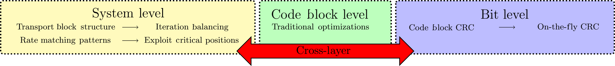
The state-of-the-art techniques which have been discussed in the previous section exclusively work on the code block level (shown green in Fig. 3). The parallel processing of the individual code blocks does not take into account the TB structure and since the decoder input is expected to be depunctured to rate 1∕3, the puncturing patterns are also not taken into account.
Figure 3 illustrates our cross-layer approach: We consider the TB structure of LTE and also the puncturing patterns on the system level and their impact on the decoding performance of the Turbo-Code decoder on code block level. For that, we focus on the PMAP decoder architecture optimized for high throughput LTE-A Turbo-Code decoding. As described in Sect. 2, the architecture consists of p sub-decoder cores working in parallel. The architecture features a CRC based iteration control and uses only one sub-decoder core for the smallest code block sizes.
3.1 Iteration balancing
With a CRC based iteration control, the decoding process is terminated early, as soon as the CRC on the decoded code word evaluates to zero. Otherwise, the decoding is continued until a maximum number of half-iterations () is reached. This is depicted in Fig. 4b, whereas Fig. 4a illustrates the case without early stopping.
For iteration balancing, the CRC based iteration control, which is used to terminate the decoding process early in the event of successful decoding, is extended to account for the TB structure on system level. Iteration balancing makes use of the fact, that most code blocks are decoded in less than half-iterations and that large code block buffers are available in the rate matching unit for the incremental redundancy of the HARQ (see Weithoffer and Wehn, 2017a). Instead of stopping the decoder after half-iterations and signaling a failed decoding if the CRC does not evaluate to zero, with iteration balancing a budged
is considered, where nCB is the number of code blocks within a TB (see Fig. 4c). By keeping track of the iterations that have been spent on previous code blocks belonging to the same TB, the Turbo-Code decoder is able to spent more decoding iterations on blocks that contain more errors, thereby using the iterations saved by the early stopping. To avoid the case where a single undecodable code block at the beginning of a TB consumes the complete iteration budget, the decoding for each code block is allowed to run for half-iterations. Our investigations have shown that this value is a very good trade-off. As can be seen in Fig. 4c and as was shown in 2017a, iteration balancing can not only be used to improve the communications performance, but can also be used to guarantee a higher throughput on system level. For this work, however, we focus on the improvement in communications performance.
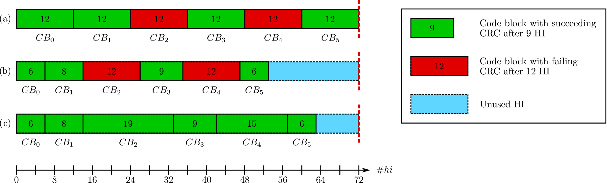
Figure 4Schedule for a TB with 6 code blocks: (a) No early stopping; (b) with early stopping; (c) Early stopping with HI Balancing.
3.2 Enhanced high-rate decoding for short blocks
For LTE, code rates are achieved by puncturing the rate 1∕3 mother Turbo-Code (see Sect. 2.2). To limit the degradation of the Turbo-Code performance at code rates as high as 0.94, not only the parity information but also the systematic information is punctured. In recent work, we identified the positions where the systematic bit is punctured away as critical bit positions (see Weithoffer and Wehn, 2017b). We could show, that, if these positions are not correctly decoded by the decoder in the first few half-iterations, the decoding process is likely to fail, since the decoder has trouble recovering the correct hard decision bit for these positions in the later half-iterations. In LTE, the critical bit positons are at the bit indices
assuming the bit indices start at i=1. At high code rates, these critical positions exhibit the majority of residual errors after Turbo-Code decoding.
The remainder of this section describes new approaches to improve the decoding performance for small code blocks at high code rates on system level. In Sect. 4, we show, for the first time, the application of these system level techniques onto a fully LTE compatible hardware architecture on bit level.
3.2.1 Improved flip-and-check
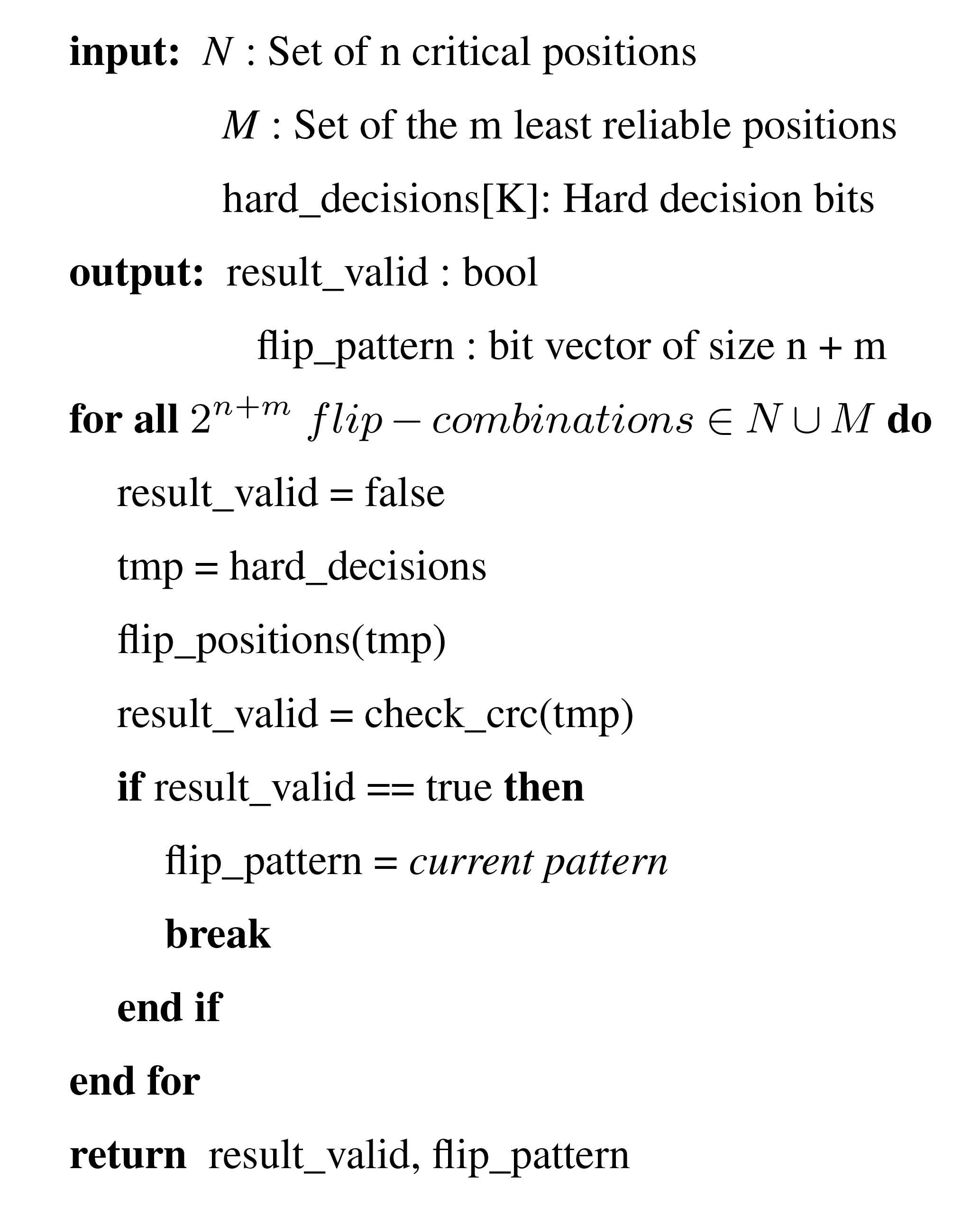
Based on the error detection via CRC, we recently proposed in 2017b the improved flip-and-check (FC) method. The algorithm shown in Fig. 5 makes use of critical positions, that result from the puncturing, to increase the communications performance of the Turbo-Code decoding with a greatly reduced complexity compared to similar approaches like event flipping Crozier and Gracie (2008) or flip-and-check Tonnellier et al. (2016). It takes as input a set N of critical positions determined by Eq. (2), a set M of least reliable bit positions with and a set of decoded hard decision bits. Then, the bits are flipped at the critical and least reliable positions for all combinations. The CRC is tested for the 2N+M patterns and the CRC results are used as stopping criterion for the iteration control of a Turbo-Code decoder. However, in a state-of-the-art hardware implementation, the complete set of hard decisions and the set of least reliable bit positions is only known after each half iteration. Therefore, in this work, we further optimized the algorithm and integrated it into an on-the-fly CRC calculation scheme (see Sect. 4).
3.2.2 Parallel improved forced symbol decoding
We use the sub-decoder cores that are not used for small code blocks to employ parallel improved forced symbol decoding. This technique, in contrast to similar techniques like enhanced forced symbol method (EFSM) (Ould-Cheikh-Mouhamedou and Crozier, 2007; Sattar et al., 2011), does not require the decoding process to be restarted after forcing symbols to a certain value. With parallel improved forced symbol decoding, one sub-decoder core decodes h half-iterations on a single sub-decoder core for small code blocks with K≤248. This allows the decoder to “warm up” the extrinsic information, i.e. improve the extrinsic information through the iterative Turbo-Code decoding. Then, each of the p available sub-decoders receives its own set of extrinsic information with symbols saturated to the maximum/minimum values at the last o critical positions, so that we get p=2o saturation patterns. Now the decoding continues in parallel on all p sub-decoder cores and the CRC is checked individually on each core after every half-iteration.
In the new architecture, the improved FC method is used for each sub-decoder and calculated on-the-fly. If more than one of the numbered sub-decoder cores have a succeeding CRC after the same half-iteration, the decoder with the lower index is chosen to provide the output. As the rate of false positives is very low for the 24 bit CRC used in LTE, this does not degrade the communications performance.
3.3 Communications performance simulations
The new LTE-A Turbo-Code decoder architecture, which will be presented in Sect. 4, incorporates for the first time enhanced event-flipping and forced symbol decoding on-the-fly to improve the communications performance for small code blocks at high code rates, as well as an iteration control with iteration balancing to improve communications performance on transport block level for high code rates. To put the communications performance into context, we performed detailed simulations to compare our new approach to other state-of-the-art Turbo-Code decoders achieving a similar throughput.
Ilnseher et al. (2012)Shrestha and Paily (2014)Roth et al. (2014)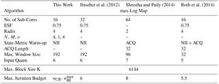
Table 1 gives the algorithm parameters of the compared decoder architectures, while Table 2 lists the implementation related data. Our investigatons have shown N=4 and M=1 to be a good match for the LTE configuration, while still allowing an integration of the new on-the-fly flip-and-check CRC calculation scheme with negligible hardware overhead. The parameter o=4 results from the usable 16=24 sub-decoder cores.
3.3.1 Impact of combined enhanced event-flipping and forced symbol decoding
Figure 6 shows the impact of the proposed enhanced event-flipping and forced symbol decoding for code block sizes and rates 8∕9, and 0.94. For those small code bock sizes, commonly only one sub-decoder core is used for the decoding of the code block. Therefore, the communications performance for the decoders listed in Table 1 is approximated by that of a non-windowed serial max-Log-Map decoder (in the following called reference decoder) with an input quantization of 6 bit, an extrinsic scaling with 0.75, which decodes for half-iterations. Frame error rate (FER) simulations have been carried out over an additive white gaussian noise (AWGN) channel with BPSK modulation.
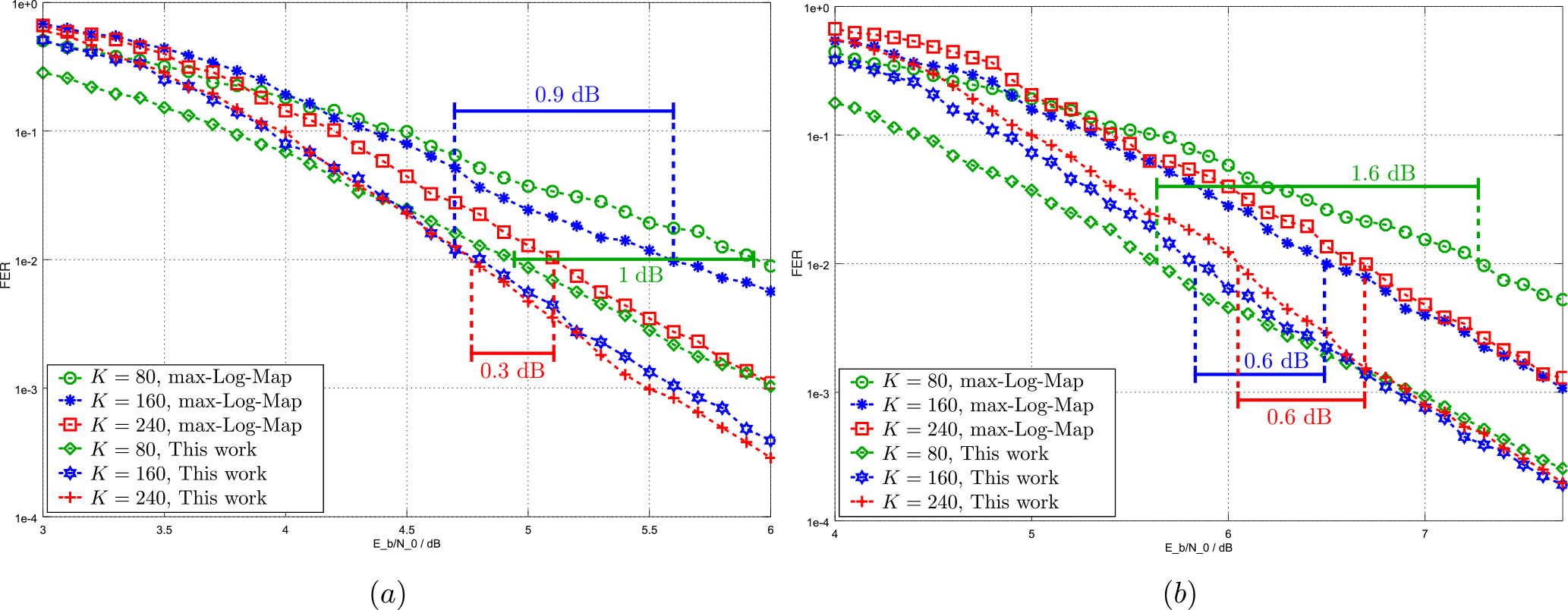
For rate 8∕9, coding gains of up to 1 dB at a target FER of 10−2 can be observed over the reference decoder when decoding blocks with K=80. Coding gains of 0.9 and 0.3 dB over the reference decoder are achieved for K=160 and K=240 respectively.
Rate 0.94 allows the largest coding gains compared to the reference with 1.6 dB for K=80 and 0.6 dB for K=160 and K=240. Note, that, due to the steaper slopes of the FER curves, the coding gains for lower target FER values will be even larger.
3.3.2 Impact of iteration balancing
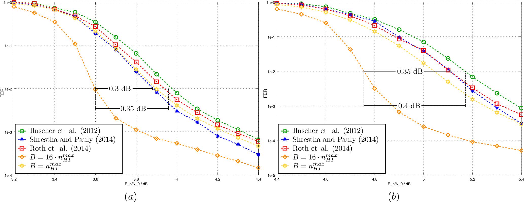
FER simulation results for a transport block size of 98 696 bit, which results in 16 code blocks of size 6144 illustrate the impact of iteration balancing for the proposed architecture in comparison to the state-of-the art architectures listed in Table 1. The decoding of 625 000 LTE-A transport blocks over an AWGN channel was simulated.
At rate 8∕9, the investigated decoders reach the target FER of 10−2 at 3.9−4 dB (see Fig. 7a). For the single code block case (i.e. ), our decoder performs similar, reaching the target FER at 3.9 dB, while achieving a coding gain of 0.3–0.35 dB for the case of 16 code blocks.
For rate 0.94, the best performing reference decoders are the decoders from Shrestha and Paily (2014) and Roth et al. (2014) (see Fig. 7b). They reach the target FER of 10−2 at an SNR of 5.1 dB while the decoder from Ilnseher et al. (2012) lies within 0.05 dB. Our decoder, if the single code block case is considered, achieves the target FER at around 5 dB. For the case of 16 code blocks, however, our decoder outperforms the reference decoders by 0.35–0.4 dB.
As stated above, we implemented the techniques for improved decoding of high rate LTE Turbo-Codes in a Turbo-Code decoder which uses the PMAP architecture with 16 sub-decoder cores. The algorithmic parameters for the architecture are listed in Table 1 of Sect. 3. An overview of the architecture is depicted in Fig. 8.
The individual sub-decoder cores use an extrinsic scaling factor (ESF, see Vogt and Finger, 2000) of 0.75 and make use of the well known radix-4 transform to reduce the amount of state metrics that need to be stored by the sub-decoder cores (see Bickerstaff et al., 2003). Next iteration Initialization (NII) is used for the state metric Initialization, a large maximum window size of 192 is used for optimal communications performance, and input values are quantized with 6 bit.
The extrinsic and the hard decision (HD) memories are split into even and odd memories due to the LTE Turbo-Code internal interleaver (odd-even splitting) and are accessed via crossbars. Memory addresses and crossbar permutation patterns are generated on-the-fly by an interleaver address generator based on the work of Ilnseher et al. (2011).
The decoder supports the complete range of LTE code block sizes from 40 to 6144 bit. This results in a maximum sub-block size of 384 bit processed by each sub-decoder core. For smaller code blocks, the sub-block size is reduced. If the code block size is smaller than 2048 bit, the number of sub-decoder cores, in other words the number of sub-blocks processed in parallel, is halved. This mitigates a decrease in communications performance due to the sub-trellises becoming to small. Similarly, for code block sizes and , 4 and 2 sub-decoder cores are used, respectively. The smallest code blocks with are decoded using parallel symbol forcing and FC. For that, all 16 sub-decoder cores are used.
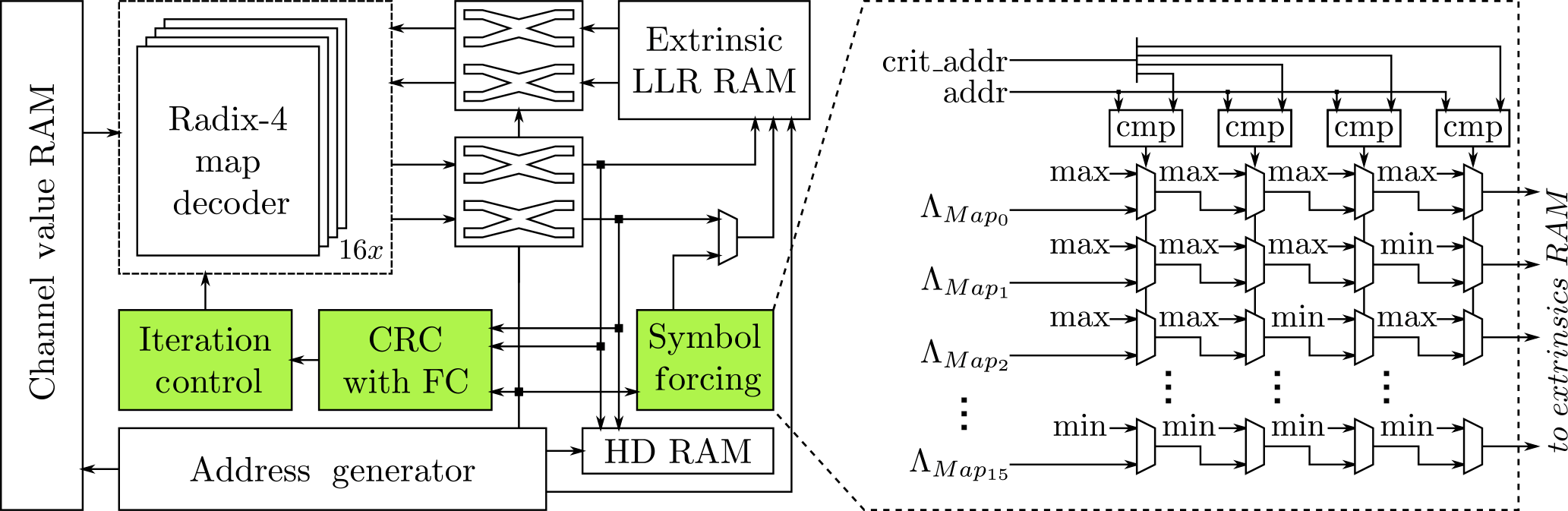
Figure 8Architecture Overview. The symbol forcin unit saturates the extrinsic information at the critical positions to the maximum and minimum possible values (see Sect. 3.2.2)
The following subsections describe in detail the integration of the parallel symbol forcing and FC. Both use as input a list of critical addresses, which is calculated from the critical positions and is dependent on the code block size K. Considering the odd-even splitting and the LTE code block sizes K resulting from the code block segmentation defined in LTE (see Third Generation Partnership Project, 2016), the calculation for the critical positons from Eq. (2) can be formulated as:
which can easily be implemted.
4.1 Parallel symbol forcing
For the smallest LTE code block sizes, i.e. , the decoder uses improved parallel symbol forcing to improve the communications performance. At design time, the available p=16 sub-decoder cores are assigned a sub-decoder index from 0–15.
While decoding, the extrinsic values at the critical positions are saturated after the first two half-iterations before being written to RAM. Saturation is performed according to a pattern that corresponds to their sub-decoder index. The extrinsic values for sub-decoder Map0, for example, will be saturated to the maximum value for all four critcal positions. Figure 8 also illustrates the symbol forcing unit.
4.2 Flip-and-check extended crc unit
Figure 9 shows the structure of the FC extended CRC unit which is based on the on-the-fly architecture we presented in 2015. This section will describe the structure of the FC extended CRC unit and give the underlying equations where appropriate. For an in-depth derivation of the on-the-fly CRC calculation scheme, the reader is referred to the original publication (see Weithoffer and Wehn, 2015).
The CRC unit calculates the CRC over the decoded code word A(x) based on the following equation:
There, G(x) is the CRC generator polynomial of degree M, p is the parallelism , is the sub-block size, Ck is the sub-block offset and Pk is the partial sub-block CRC. In our case, it is G(x)=CRC24B for which M=24 (see also Third Generation Partnership Project, 2016), p=16. A table lookup is used to realize the from Eq. (4) and this lookup table is initialized at the beginning of the decoding (Ck LUT in Fig. 9).
Ilnseher et al. (2012)Shrestha and Paily (2014)Roth et al. (2014)
The sub-block CRCs Pk for the sub-blocks are calculated according to
Dedicated blocks are used to calculate the partial CRCs CRCeven and CRCodd for the hard decision bits akS+δ(2l) and respectively. The bit index offset for the kth sub-block is given by k⋅S and the function δ(l) describes the bit index offset within the sub-blocks according to
For efficient implementation, the sub-block internal bit index offset is broken down into (Divide by M in Fig. 9). Using these, CRCeven and CRCodd are calculated with a combination of table lookup and dedicated block.
The FC extensions, which are used for the code blocks with , consist of three parts:
-
Selectively storing the partial CRCs for the critical positions,
-
finding the most unreliable bit position and stroring the according partial CRC, and
-
calculating the list of partial CRC combinations.
The partial CRCs for the critical positions are selected according to addreven and stored in registers during the decoding phase. Note, that none of the partial CRCs for the critical positions are added to the Pk registers, which for serve as registers for the intermediate CRC result of each of the 16 sub-decoder cores.
The most unreliable bit position is selected and stored in parallel to the decoding, and individually for each sub-decoder core. If the current LLR-input to the CRC unit is of smaller magnitude than the previously stored one and the bit position is not included in the set of critical positions, the bit position (calculated from the address), its magnitude and its partial CRC are stored in registers. The same happens, when the magnitude is identical, but the bit index is smaller. Lastly, after decoding, the list of the different combined sums of partial CRCs for the critical positions and the position with the minimum LLR is compiled and sent to the iteration control.
4.3 Iteration control
The iteration control uses iteration balancing with a configurable budget of B≤192 half-iterations (see Sect. 2.1). For transport blocks with more than one code block, the budget is reset at the start of the transport block. Transport blocks consisting of one code block use a budget of 12 half-iterations.
For all code block sizes, a CRC based early stopping is used. If the output from the CRC unit evaluates to 0 after the decoding of a half-iteration has finished, i.e. the CRC check is passed successfully, the decoding process is terminated early.
For code blocks with size , however, a list of 32 CRC results is passed from each sub-decoder core. The decoding process is then terminated early if (at least) one decoder core has (at least) one succeeding CRC in the according list. If there are more than one successful CRCs whithin a list, the successful CRC with the smallest list index is chosen as the valid solution. Similarly, if there are more than one sub-decoder cores with a successful CRC in the same half-iteration, the result of the sub-decoder with the lower index is chosen as the correct result.
From the selected result, a correction pattern is generated and the address of the weakest LLR position is send to the output of the Turbo-Code decoder. Thereby, the hard decision bits can be corrected on-the-fly when they are read from the hard decision memory.
The architecture described in Sect. 4 was implemented in VHDL. Synthesis was done with Synopsys Design Compiler and place and route with Synopsys IC Compiler on 28 nm Global Foundries FDSOI technology. Worst case PVT (process/variation/time) conditions were assumed for synthesis and place and route and the power estimation was carried out the back-annotated netlist post place and route.
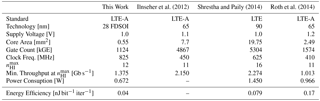
Our architecture achieves a maximum frequency of 825 MHz leading to a minimum throughput of 1.375 Gb s−1 for the largest LTE code block size K=6144 and a budget of (see Sect. 3.1). Power consumption yields 0.672 W under nominal conditions (1.0 V, 25 ∘C), which translates to an energy efficiency of 0.04 nJ bit−1 iter−1.
Table 2 lists the results of this work along with other reported LTE Turbo-Code decoder implementations achieving a throughput of more than 1 Gbb s−1. However, since these contain results from different technology nodes, a fair comparison of area and throughput is difficult because normalization is not straightforward. Thus, the numbers are given “as is” and the comparison is performed only for gate count and energy efficiency.
Among the other reported implementations, only Roth et al. (2014) specifically aimed for a support of high code rates, while Ilnseher et al. (2012) and Shrestha and Paily (2014) aimed at high throughput. The presented Turbo-Code decoder has the lowest gate count and the best energy efficiency of all listed implementations.
The flexibility of todays communication standards with respect to code rates and code block sizes requires a special consideration of high code rates for the architecture design. In this paper, we show, how cross-layer considerations can be used to improve the communication performance of Turbo-Code decoder hardware architectures beyond the state-of-the-art, which only considers optimizations on code block level.
The fully LTE compatible Turbo-Code decoder architecture we present employs techniques which use knowledge from the system level and combines them with a CRC calculation technique on the bit level: The combined improved flip-and-check/forced symbol decoding for small code blocks and iteration balancing on transport block level both improve the communication performance for high code rates. For code block sizes with K < 248, combined improved flip-and-check/forced symbol decoding is used and coding gains of more than 1.5 dB are achieved, while on transport block level, the use of iteration balancing yields coding gains of up to 0.4 dB for high code rates.
To the best of our knowledge, a hardware implementation of these techniques is demonstrated for the first time. Post place and route results, obtained for 28 nm FDSOI technology, show the architecture to be competetive in terms of throughput (1.375 Gb s−1), area (0.55 mm2) and energy efficiency (0.04 nJ bit−1 iter−1).
All data are represented in the text and functions. The raw data is not meaningfully interpretable without the use of special simulation/synthesis tools which are not publicly available.
The authors declare that they have no conflict of interest.
This article is part of the special issue “Kleinheubacher Berichte 2017”. It is a result of the Kleinheubacher Tagung 2017, Miltenberg, Germany, 25–27 September 2017.
We gratefully acknowledge financial support by the EU (project-ID:
760150-EPIC).
Edited by: Jens
Anders
Reviewed by: two anonymous referees
Belfanti, S., Roth, C., Gautschi, M., Benkeser, C., and Huang, Q.: A 1Gbps LTE-advanced turbo-decoder ASIC in 65nm CMOS, in: VLSI Circuits (VLSIC), 2013 Symposium on, C284–C285, 2013. a, b
Bickerstaff, M., Davis, L., Thomas, C., Garrett, D., and Nicol, C.: A 24Mb/s Radix-4 LogMAP Turbo Decoder for 3GPP-HSDPA Mobile Wireless, in: Proc. 2003 IEEE International Solid-State Circuits Conference (ISSCC '03), 150–484, vol. 1, San Francisco, CA, USA, https://doi.org/10.1109/ISSCC.2003.1234244, 2003. a
Crozier, S. and Gracie, K.: Improving the flare performance of turbo codes using error detection and event flipping, in: 2008 5th International Symposium on Turbo Codes and Related Topics, 266–271, https://doi.org/10.1109/TURBOCODING.2008.4658709, 2008. a
Dahlman, E., Parkvall, S., Skold, J., and Beming, P.: 3G evolution: HSPA and LTE for mobile broadband, Academic press, Oxford, 2010. a
Dielissen, J. and Huiskens, J.: State Vector Reduction for Initialization of Sliding Windows MAP, in: Proc. 2nd International Symposium on Turbo Codes & Related Topics, Brest, France, 387–390, 2000. a
Ilnseher, T., May, M., and Wehn, N.: A Multi-Mode 3GPP-LTE/HSDPA Turbo Decoder, in: Proc. IEEE International Conference on Communication Systems (ICCS 2010), 336–340, 2010. a
Ilnseher, T., May, M., and Wehn, N.: A Monolithic LTE Interleaver Generator for Highly Parallel SMAP Decoders, in: Proc. Tenth Annual Wireless Telecommunications Symposium (WTS 2011), 2011. a
Ilnseher, T., Kienle, F., Weis, C., and Wehn, N.: A 2.12Gbit/s Turbo Code Decoder for LTE Advanced Base Station Applications, in: 2012 7th International Symposium on Turbo Codes and Iterative Information Processing (ISTC) (ISTC 2012), Gothenburg, Sweden, 2012. a, b, c, d, e, f
Li, A., Hailes, P., Maunder, R. G., Al-Hashimi, B. M., and Hanzo, L.: 1.5 Gbit/s FPGA Implementation of a Fully-Parallel Turbo Decoder Designed for Mission-Critical Machine-Type Communication Applications, IEEE Access, 4, 5452–5473, https://doi.org/10.1109/ACCESS.2016.2599408, 2016a. a
Li, A., Xiang, L., Chen, T., Maunder, R. G., Al-Hashimi, B. M., and Hanzo, L.: VLSI Implementation of Fully Parallel LTE Turbo Decoders, IEEE Access, 4, 323–346, https://doi.org/10.1109/ACCESS.2016.2515719, 2016b. a
Ould-Cheikh-Mouhamedou, Y. and Crozier, S.: Improving the Error Rate Performance of Turbo Codes using the Forced Symbol Method, IEEE Commun. Lett., 11, 616–618, https://doi.org/10.1109/LCOMM.2007.070171, 2007. a
Cerwall, P., Carson, S., and Lundvall, A.: Ericsson Mobility Report November 2016, https://www.ericsson.com/en/mobility-report/reports (last access: 15 March 2018), 2016. a
Robertson, P., Villebrun, E., and Hoeher, P.: A Comparison of Optimal and Sub-Optimal MAP decoding Algorithms Operating in the Log-Domain, in: Proc. 1995 International Conference on Communications (ICC '95), Seattle, Washington, USA, 1009–1013, 1995. a
Roth, C., Belfanti, S., Benkeser, C., and Huang, Q.: Efficient Parallel Turbo-Decoding for High-Throughput Wireless Systems, IEEE T. Circuits I, 61, 1824–1835, https://doi.org/10.1109/TCSI.2013.2290831, 2014. a, b, c, d, e
Sattar, Z., Al-Sanie, A. M., and Ould-Cheikh-Mouhamedou, Y.: Enhanced Forced Symbol Method for improving the error rate performance of turbo codes, in: Electronics, Communications and Photonics Conference (SIECPC), 2011 Saudi International, 1–5, https://doi.org/10.1109/SIECPC.2011.5876993, 2011. a
Shrestha, R. and Paily, R. P.: High-Throughput Turbo Decoder With Parallel Architecture for LTE Wireless Communication Standards, IEEE T. Circuits I, 61, 2699–2710, https://doi.org/10.1109/TCSI.2014.2332266, 2014. a, b, c, d, e, f
Sun, Y. and Cavallaro, J.: Efficient hardware implementation of a highly-parallel 3GPP LTE/LTE-advance turbo decoder, Integration VLSI Journal, 44, 305–315, https://doi.org/10.1016/j.vlsi.2010.07.001, 2010. a
Third Generation Partnership Project: LTE; Evolved Universal Terrestrial Radio Access (E-UTRA); Multiplexing and channel coding (3GPP TS 36.213 version 13.1.0 Release 13), 2016. a, b, c, d
Tonnellier, T., Leroux, C., Gal, B. L., Gadat, B., Jego, C., and Wambeke, N. V.: Lowering the Error Floor of Turbo Codes With CRC Verification, IEEE Wireless Commun. Le., 5, 404–407, https://doi.org/10.1109/LWC.2016.2571283, 2016. a
Vogt, J. and Finger, A.: Improving the Max-Log-MAP Turbo Decoder, IEEE Electronic Letters, 36, 1937–1939, 2000. a
Wang, G., Shen, H., Sun, Y., Cavallaro, J. R., Vosoughi, A., and Guo, Y.: Parallel Interleaver Design for a High throughput HSPA+/LTE Multi-Standard Turbo Decoder, IEEE T. Circuits I, 61, 1376–1389, https://doi.org/10.1109/TCSI.2014.2309810, 2014. a, b
Weithoffer, S. and Wehn, N.: Latency reduction for LTE/LTE-A turbo-code decoders by on-the-fly calculation of CRC, in: Personal, Indoor, and Mobile Radio Communications (PIMRC), 2015 IEEE 26th Annual International Symposium on, 1409–1414, https://doi.org/10.1109/PIMRC.2015.7343519, 2015. a
Weithoffer, S. and Wehn, N.: Latency Reduced LTE-A Turbo-Code Decoding with Iteration Balancing on Transport Block Level, in: SCC 2017; 11th International ITG Conference on Systems, Communications and Coding, 2017a. a, b
Weithoffer, S. and Wehn, N.: Enhanced decoding for high-rate LTE Turbo-Codes with short block lengths, in: 2017 IEEE International Conference on Communications Workshops (ICC), 2017b. a, b