 | 04 Sep 2018
Polar Code decoder exploration framework
Claus Kestel
Stefan Weithoffer
Norbert Wehn
The increasing demand for fast wireless communications requires sophisticated baseband signal processing. One of the computational intense tasks here is advanced Forward Error Correction (FEC), especially the decoding. Finding efficient hardware implementations for sophisticated FEC decoding algorithms that fulfill throughput demands under strict implementation constraints is an active research topic due to increasing throughput, low latency, and high energy efficiency requirements.
This paper focuses on the interesting class of Polar Codes that are currently a hot topic. We present a modular framework to automatically generate and evaluate a wide range of Polar Code decoders, with emphasis on design space exploration for efficient hardware architectures. To demonstrate the efficiency of our framework a very high throughput Soft Cancellation (SCAN) Polar Code decoder is shown that was automatically generated. This decoder is, to the best of our knowledge, the fastest SCAN Polar Code decoder published so far.


Over the last decades, digital communication systems became an essential part of our lives. We consume, produce, and store an ever increasing amount of data. Their transport requires fast networks and advanced baseband signal processing to handle the growing amount of wireless traffic. Here, the demand for high energy efficiency, low latency, and high throughput is increasing. One crucial and challenging part of communication systems is channel coding, or FEC, that copes with transmission errors in noisy environments (Weithoffer et al., 2017).
A class of codes, that gained much interest in the last years for achieving the channel capacity (Shannon, 1948) for specific channels, are Polar Codes. This property and their subsequent adoption for the next generation mobile networks (5G) has put Polar Codes in the focus of many investigations. In this paper we only focus on the decoding because it's the most computationally intense part.
Various hardware implementations for Polar Code decoders have been proposed in recent years. They cover pipelined high-throughput architectures (Giard et al., 2017), flexible (Dizdar and Arıkan, 2016), and iterative decoder implementations (Park et al., 2014) to name but a few of them. These decoders are generally optimized only for one specific target, e.g., throughput, area or code rate flexibility, and especially for only one specific decoding algorithm. Moreover, a thorough analysis and comparison of the various architectures with respect to trade-offs is missing from literature.
In this paper, we present a framework for fast exploration of the design space for Polar Code decoder hardware implementations. The framework also allows the fast adaption to changing requirements, i.e., the code structure during the standardization of 5G.
The contributions are as follows: First, we propose Polar Factor Trees as a generalized model of Polar Code decoding. Based on the Polar Factor Tree, we present an architectural template for high-throughput Polar Code decoders. The Polar Factor Tree and the architectural template are the basis of our framework. Second, we present a framework that allows fast exploration of the Polar Code decoder design space. Output are detailed design metrics (throughput, area, etc.). And third, as a proof-of-concept of our framework, we present the first high-throughput SCAN Polar Code decoder that achieves more than 100 Gbps on a 28 nm technology.
The paper is structured as follows: In Sect. 3 a short introduction to Polar Codes, their encoding and decoding algorithms is given. Section 4 focuses on high-throughput decoder architectures. In Sect. 5 the proposed framework and the generated SCAN Polar Code decoder are presented.
Polar Codes, invented 2009 by Erdal Arikan, are the first codes proven to achieve channel capacity (Arikan, 2009) for Binary Symmetric Memoryless Channels (BSMC). Polar Codes are block codes and belong to the class of multilevel concatenated codes, but, in contrast to the similar Reed-Muller-Codes, they use the phenomenon of channel polarization to maximize coding efficiency. As a candidate for the FEC of the next generation mobile networks (5G) they play an important role in the ongoing standardization process.
3.1 Channel polarization
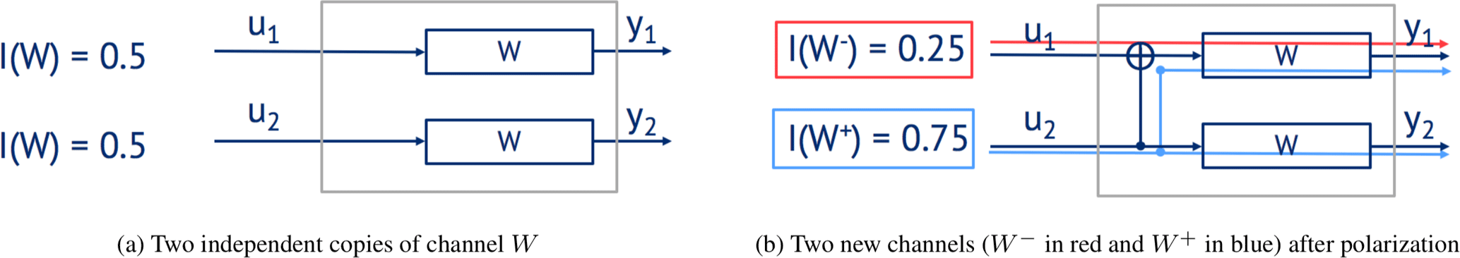
Channel polarization is a transformation of N independent copies of a channel W into a new set of N channels , where, for large N, the symmetric channel capacity approaches either 0 (completely noisy) or 1 (completely error-free). Figure 1 shows an example for a set of two channels before and after the polarization. The channel with decreased capacity is called W− (red), and the other with the improved capacity is called W+ (blue).
3.2 Code construction
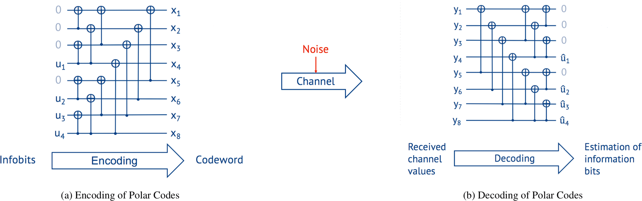
The butterfly structure in Fig. 1b represents the smallest possible Polar Code with N=2. Larger codes can be built by recursively combining two codes of length N∕2 to a new code of length N. Therefore, to create a code of length N, steps of combining are necessary. The code rate N∕K is then selected by setting the least reliable channels to fixed known values, e.g., 0 (called frozen bits), and using the more reliable channels to transmit the information bits. Figure 2 shows the structure of a Polar Code of length N=8 and K=4 information bits u1…4. The frozen bits are set to 0.
Polar Codes are defined with a generator matrix GN that is built by using the Kronecker power of . Note that F2 represents the butterfly structure of Fig. 1b, and the Kronecker power equals the combination of smaller codes into bigger ones.
3.3 Encoding
The encoding is shown in Fig. 2a for a Polar Code. A sequence of information bits u1…4 and frozen bits is passed through the code structure from left to right to get a codeword x1…8 of length N=8. Formally, the encoding is x=uGN with GN being the generator matrix and u the information vector that includes the frozen bits.
3.4 Decoding
The decoding of Polar Codes can be seen as the reversal of the encoding. Thus, decoding passes the received channel values y from left to right as shown in Fig. 2b.
But while the encoding is simply a linear transformation, the decoding is the estimation of the originally transmitted information bits from the received channel values y, commonly represented as Log Likelihood Ratios (LLRs). LLRs are a measure of the probability of a received value corresponding to either 0 or 1 and are defined as . This estimation can be done by different algorithms.
The most popular decoding algorithm for Polar Codes is the Successive Cancellation (SC) algorithm that was presented by Arikan (2009) in his original paper. SC passes the received channel values from left to right over the Polar Factor Graph in Fig. 2b. Four types of operations have to be performed for every butterfly structure (see Sect. 4.1). The decoding of the individual bits is performed in a recursive manner on the Polar Factor Graph.
An extension of SC is the Successive Cancellation List (SCL) algorithm. In this algorithm a list of L most probable decisions are considered, i.e., L codewords are decoded. The final codeword is selected out of the list by, e.g., the highest overall probability or by other checks like a Cyclic Redundancy Check (CRC). The SC and SCL are sequential algorithms.
An inherently parallel decoding algorithm is the Belief Propagation (BP) algorithm for Polar Codes. It iterates from left to right and reverse over the Polar Code Factor Graph from Fig. 2b. Thus, the bits are decoded in an iterative manner similar to the BP for Low Density Parity Check (LDPC) codes. However, Abbas et al. (2017) showed that up to 100 iterations are necessary to match the error correcting performance of the SC algorithm.
The SCAN algorithm (Fayyaz and Barry, 2014) uses the general processing order of the SC algorithm in combination with the exchange of soft values from the BP algorithm. The SCAN decoding algorithm is highly parameterizable in terms of processing order of the nodes and allows various trade-offs.
Figure 3 shows the communications performance of the SC, SCL, and SCAN algorithms, respectively. While SC and SCAN provide similar communications performance and mostly differ in the hard or soft output, the SCL algorithm performs significantly better, but at the cost of increased decoding complexity. The SCL was simulated with list size L=4 and the SCAN algorithm with one iteration I=1 for a code of over an AWGN channel and floating-point arithmetic. The Polar Code was constructed by using the gaussian approximation method (Vangala et al., 2015) for a design Signal-to-Noise Ratio (SNR) of 0 dB.
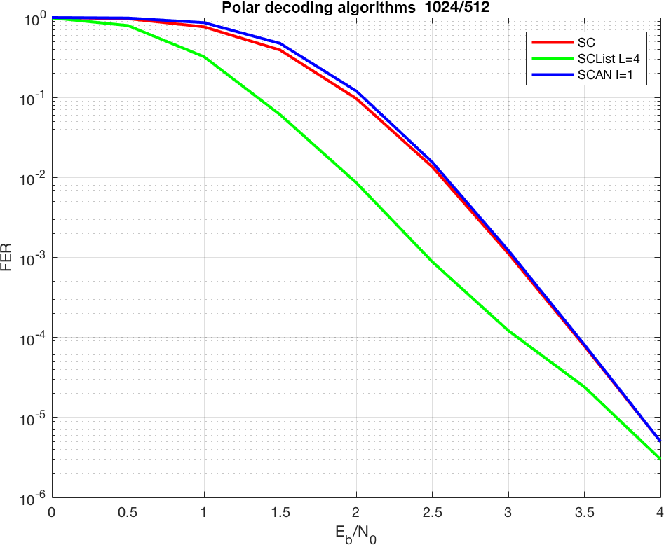
Figure 3Error Correction Performance in Frame Error Rate (FER) over the SNR in Eb∕N0 for a Polar Code of .
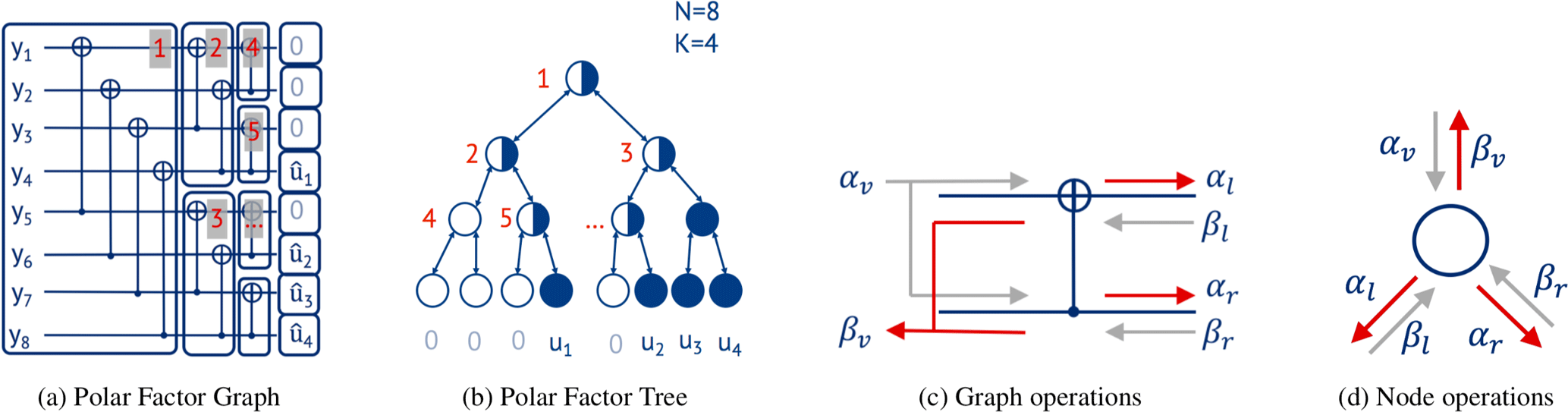
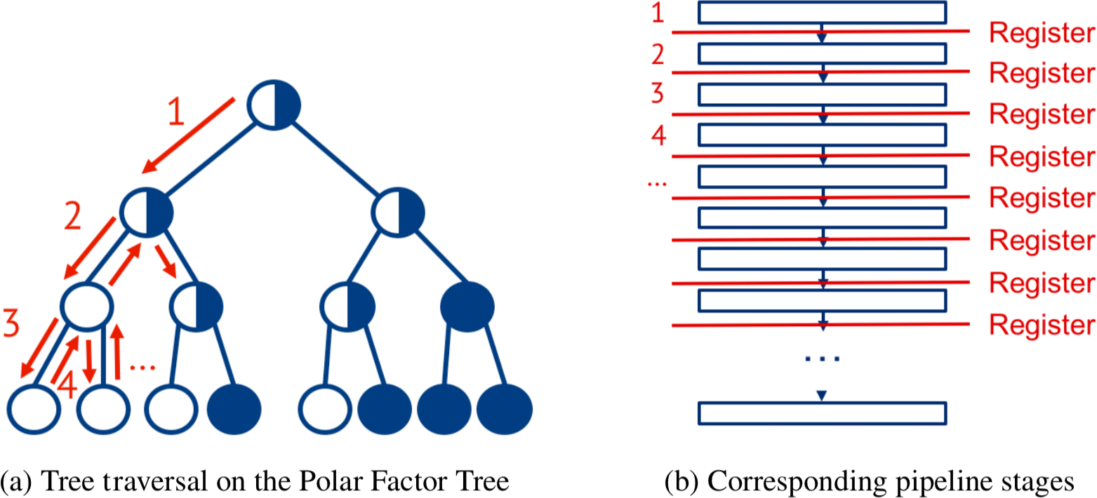
In Sect. 3 we used the Polar Factor Graph to explain decoding. A compressed version of this graph is the Polar Factor Tree (see Fig. 4a, b). For that, groups of concurrent calculation steps are combined and represented as a single node in the tree. A row of operations is mapped on the same tree level. Leaf nodes, which are frozen, are marked white (in Fig. 4b), leaf nodes containing information bits blue. Non-leaf nodes containing only frozen or information bits as child nodes are marked white and blue, respectively. Nodes with mixed leaf nodes are colored half white and half blue.
SC, SCL, and SCAN decoding can be modeled by a depth-first search on this tree. Whenever during search a node is visited, a corresponding operation has to be performed. BP corresponds to a breadth-first search on the same tree.
The factor tree is a better representation than the graph representation and used in many approaches: Alamdar-Yazdi and Kschischang (2011), Sarkis et al. (2014), Sarkis et al. (2016), and Lin et al. (2017). We use the Polar Factor Tree as central data structure for our framework.
4.1 Node operations
As said, all decoding algorithms can be mapped onto a depth- (SC, SCL, SCAN) or breadth-first search (BP) on this Polar Factor Tree. Here we focus on the first class of algorithms. The differences in the three decoding algorithm is in the node operations while the tree is traversed.
Figure 4c and d show the performed operations of one butterfly unit and one node, respectively. αv, βl, and βr denote vectors that are input to a node (marked in gray). αl, αr, and βv are corresponding vectors calculated by the node (marked red). The notation with is used to address one element of the corresponding vector. The dimensions of the vectors depend on the tree level t, starting with t=0 for the root node. For the vectors αv and βv the length is N∕2t and for αl, βl, αr, and βr the length is .
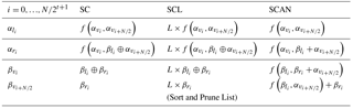
Every node (Fig. 4d) that is visited during depth-first search first calculates a new vector of LLRs αl and sends it to the left child. In the backtracking phase of the search, the left child provides βl to this node. Next, αr is calculated and sent to the right child, awaiting the result βr of the right child. Finally βv is calculated and sent to its parent node. Table 1 shows the corresponding equations for the calculation of the vectors αl, αr, and βv for the SC, SCL, and SCAN decoding algorithms, respectively. ⊕ denotes the binary addition and × implying that the operation has to be performed L times.
Please note that for SCL decoding algorithm, additional effort has to be spent within the nodes for the list management, in particular the sorting and pruning of the list according to path metrics which are not shown here for simplicity. Also, the leaf operations differ slightly between SC, SCL, and SCAN. While SC and SCL decide for either 1 or 0 in the leaf node, the SCAN decoding algorithm follows the BP approach for Polar Codes and propagates constants, i.e., infinity for frozen bits and zero for information bits.
4.2 Unrolling the tree traversal
To build high-throughput decoders, pipelining is the most efficient way to gain maximal parallelism and at the same time maximized data locality. For iterative decoding algorithms like the BP, pipelining can be achieved by unrolling the iterations and pipelining the different stages. The number of pipelining stages corresponds to the number of iterations. Such an architecture was for the first time demonstrated for LDPC decoding by Schläfer et al. (2013). In their paper, a min-sum LDPC decoding algorithm was unrolled over 9 iterations for an LDPC code, achieving an outstanding throughput and energy efficiency, but at the cost of flexibility.
Here we focus on SC, SCL, and SCAN that perform depth-first traversal of the Polar Factor Tree during decoding. Comparable to unrolled LDPC decoding, we can similarly unroll the tree traversal: Whenever a tree node is visited during the traversal, a corresponding pipeline stage is instantiated. The resulting generic architectural template is shown in Fig. 5: Panel a shows the tree traversal and panel b the corresponding pipeline stages. This model serves as a generic model for all decoding algorithms that traverse the tree, i.e., SC, SCL, and SCAN. The only difference between decoders for different algorithms is in the node operations in the pipeline stages.
For a binary balanced tree with N leaf nodes, node-visits are performed during the depth-first traversal which results in pipeline stages, respectively.
Giard et al. (2015) have first published this concept of unrolling for Polar Codes and the SC algorithm. Later it was presented by Giard et al. (2016) also for the SCL algorithm. Our approach presented in this paper is a generalized model and valid for all decoding algorithms based on the traversal of the Polar Factor Tree.
4.3 Pipeline optimization
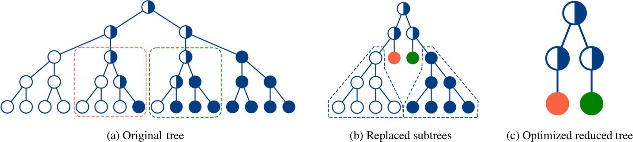
Since the number of traversed nodes' visits directly maps into the amount of pipeline stages, minimizing the tree corresponds to minimizing the number of pipeline stages. A smaller tree therefore leads to less pipeline stages, thus lower latency, improved area, and energy efficiency. Sarkis et al. (2014) have proposed some techniques to reduce the size of the Polar Factor Tree without a loss in error correction performance.
Lin et al. (2017)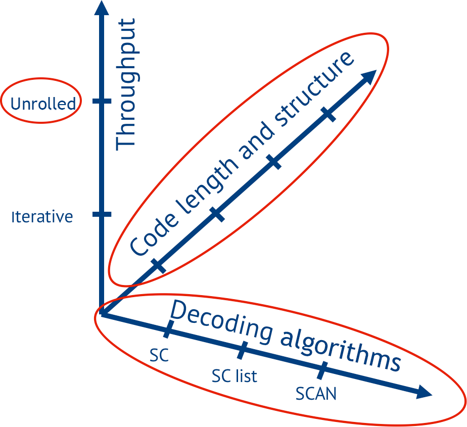
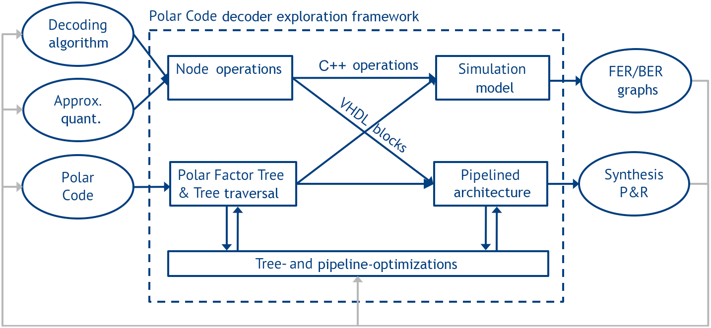
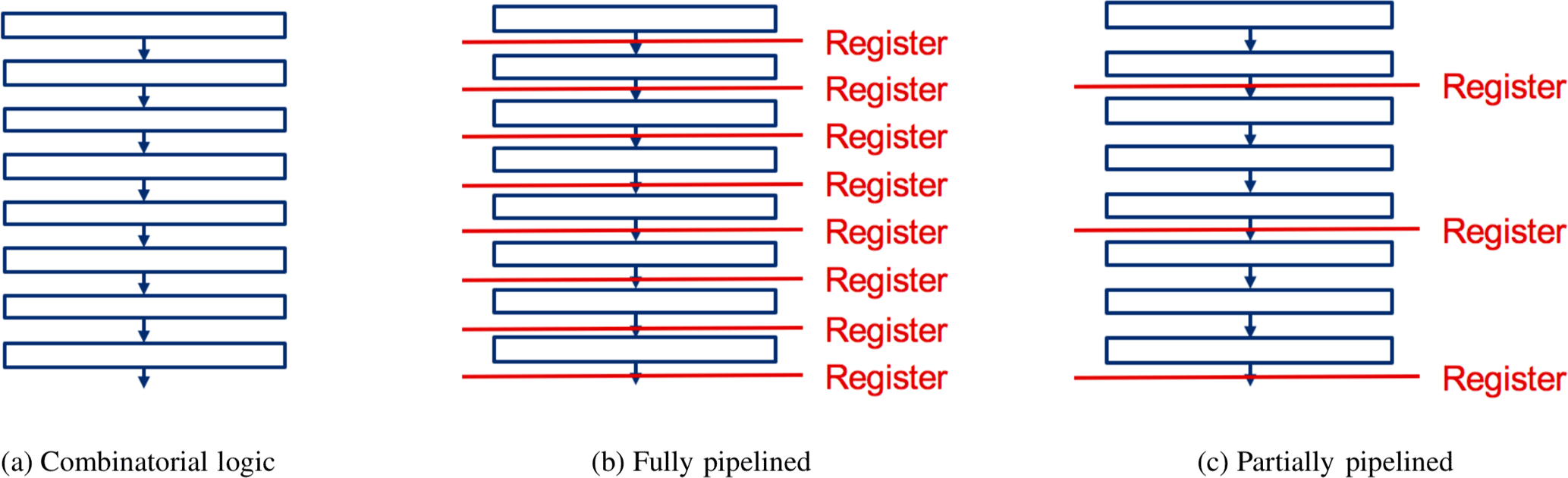
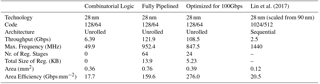
Table 3Implementation results for a SCAN decoder with for different architectures on a 28 nm FD-SOI technology
A reduction is achieved by first replacing complete subtrees with a single node that can decode the subtree in one step. Two possible subtree optimizations are shown in Fig. 6: A 4 bit subtree with three frozen and one information bit as leaves, equaling a repetition code, is replaced by a new specialized node (marked red). Similar a 4 bit subtree with only one frozen bit and three information bits as leaves, acting like a simple parity check code, is likewise replaced by a new specialized node (marked green).
The tree can be further reduced by optimizing homogeneous subtrees (composed of either completely frozen or completely information nodes) and merging them into their parent node. This is valid because a subtree with only frozen bit leaves (marked white in Fig. 6) equals a Rate-0 code, that doesn't carry any information but only noise. Accordingly a subtree with only information bits as leaves (marked blue) equals a Rate-1 code that consists of only information and no redundancy, therefore has no error correction capabilities.
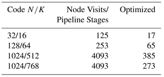
Table 2 shows the number of node visits, or pipeline stages, for selected Polar Codes with different code lengths and code rates, respectively, before and after the optimization for the SCAN decoding algorithm. The numbers for the optimized pipeline stages are created by traversing the reduced tree described in this section. While the improvement in the number of pipeline stages and therefore also latency and area are significant, it also becomes obvious, that every change in the code length or code rate results in a different tree and, thus, a different architecture.
Every change in either the decoding algorithm, the code (the position of frozen bits), its length or rate affects the optimal architecture for a Polar Code decoder and spans a design space (Fig. 7) of possible architectures. This space is too large for manual investigation and can only be explored by automating the hardware decoder generation.
We developed a framework to explore this design space. Input are a Polar Code, a specific decoding algorithm, and further parameters, e.g., approximations, quantization, etc. Output are simulation results to evaluate the error correction performance and VHDL code of decoder architectures that can be synthesized, placed&routed. This information is fed back into the framework for further optimization. The framework consists of a number of different components that are modular and interact as shown in Fig. 8. Their functionality is as follows:
Node Operations: In this block, the node functionality is selected according to the decoding algorithm. The node functionality is defined on C++ level for simulation and on VHDL level for architecture generation (Table 1).
The Simulation Model generates the error correction performance for the specified decoding algorithms, approximations, quantization etc., and generates FER/Bit Error Rate plots as shown in Fig. 3.
The Polar Factor Tree from Sect. 4 represents the main data structure of the framework and uses a Polar Code as input. The tree is then traversed to generate a Pipelined Architecture (see Sect. 4.2). This pipelined architecture uses the sequence of operations from the tree traversal and the VHDL blocks to assemble a fully synthesizable Polar Code decoder in VHDL.
Both the Polar Factor Tree and the pipelined architecture are subject to Optimization based on results from the simulation model and synthesis/place&route. For the Polar Factor Tree this can be, e.g., optimizations on the tree (see Sect. 4.3). For pipeline optimizations we refer to the next section.
5.1 Case study
To show the performance of our framework we present as a case study, an unrolled SCAN Polar Code decoder with one iteration. We further show various design trade-offs. There are two extreme cases. We can remove all registers from the pipeline stages. This results in a pure combinatorial circuit (Fig. 9a). Advantages are low area, low power, and low latency. Main disadvantage is low throughput. The other extreme is to have a pipeline register between each stage (Fig. 9b). Advantage is high-throughput, disadvantages are high area, high power, and a high latency. Our framework allows to balance the register count between the two extrema using its internal timing engine. So, for a given throughput constraint, the number and optimum position of registers can be automatically calculated (Fig. 9c). Table 3 shows the various trade-offs. Results are after place&route and worst case Process-Voltage-Temperature (PVT) on a 28 nm FD-SOI technology. Throughput refers to coded bits.
The first two columns show the pure combinatorial and fully pipelined architecture, respectively. Column 3 shows the architecture for a throughput constraint of 100 Gbps. All three architectures were automatically generated with our framework. The last column shows the fastest SCAN decoder implementation published (Lin et al., 2017). However, their decoder uses a sequential processing, a different code and a different technology. To give at least a first estimate we scaled the decoder down to 28 nm. Our architecture is more than 40 times faster and shows a much better area efficiency,
To the best of our knowledge, this fully pipelined architecture is the fastest SCAN Polar Code decoder, while the partially pipelined architecture is the most area efficient published so far.
Based on the works of Sarkis et al. (2014), Giard et al. (2015), and Lin et al. (2017) we proposed a generalized model for the decoding of Polar Codes with the SC, SCL, and SCAN algorithms. This model is used to provide a generic architectural template for unrolled high-throughput decoders. We further presented a framework to evaluate the error correction performance of Polar Codes, automate the unrolling and generate a fully functional and synthesizable VHDL implementation of a Polar Code decoder.
Further, we presented an optimization of pipeline stages to improve the area and energy efficiency. To demonstrate the performance of our framework we presented a high throughput SCAN decoder. With a throughput of over 100 Gbps it is to our knowledge the fastest published SCAN decoder.
All data are represented in the text and functions. The raw data is not meaningfully interpretable without the use of special simulation/synthesis tools which are not publicly available.
The authors declare that they have no conflict of interest.
This article is part of the special issue “Kleinheubacher Berichte 2017”. It is a result of the Kleinheubacher Tagung 2017, Miltenberg, Germany, 25–27 September 2017.
We gratefully acknowledge financial support by the DFG (project-ID:
2442/8-1) and the EU (project-ID: 760150-EPIC).
Edited by: Jens Anders
Reviewed by: two anonymous referees
Abbas, S. M., Fan, Y., Chen, J., and Tsui, C. Y.: High-Throughput and Energy-Efficient Belief Propagation Polar Code Decoder, IEEE T. VLSI Syst., 25, 1098–1111, https://doi.org/10.1109/TVLSI.2016.2620998, 2017. a
Alamdar-Yazdi, A. and Kschischang, F. R.: A Simplified Successive-Cancellation Decoder for Polar Codes, IEEE Commun. Lett., 15, 1378–1380, https://doi.org/10.1109/LCOMM.2011.101811.111480, 2011. a
Arikan, E.: Channel Polarization: A Method for Constructing Capacity-Achieving Codes for Symmetric Binary-Input Memoryless Channels, IEEE T. Inform. Theory, 55, 3051–3073, https://doi.org/10.1109/TIT.2009.2021379, 2009. a, b
Dizdar, O. and Arıkan, E.: A High-Throughput Energy-Efficient Implementation of Successive Cancellation Decoder for Polar Codes Using Combinational Logic, IEEE T. Circuit. S.-I, 63, 436–447, https://doi.org/10.1109/TCSI.2016.2525020, 2016. a
Fayyaz, U. U. and Barry, J. R.: Low-Complexity Soft-Output Decoding of Polar Codes, IEEE J. Sel. Area. Comm., 32, 958–966, https://doi.org/10.1109/JSAC.2014.140515, 2014. a
Giard, P., Sarkis, G., Thibeault, C., and Gross, W. J.: 237 Gbit/s unrolled hardware polar decoder, Electron. Lett., 51, 762–763, https://doi.org/10.1049/el.2014.4432, 2015. a, b
Giard, P., Balatsoukas-Stimming, A., Müller, T. C., Burg, A., Thibeault, C., and Gross, W. J.: A multi-Gbps unrolled hardware list decoder for a systematic polar code, 50th Asilomar Conference on Signals, Systems and Computers, 1194–1198, https://doi.org/10.1109/ACSSC.2016.7869561, 2016. a
Giard, P., Balatsoukas-Stimming, A., Müller, T. C., Bonetti, A., Thibeault, C., Gross, W. J., Flatresse, P., and Burg, A.: PolarBear: A 28-nm FD-SOI ASIC for Decoding of Polar Codes, IEEE J. Em. Sel. Top. C., 7, 616–629, https://doi.org/10.1109/JETCAS.2017.2745704, 2017. a
Leroux, C., Tal, I., Vardy, A., and Gross, W. J.: Hardware architectures for successive cancellation decoding of polar codes, Int. Conf. Acoust. Spee., 1665–1668, https://doi.org/10.1109/ICASSP.2011.5946819, 2011. a
Lin, J., Yan, Z., and Wang, Z.: Efficient Soft Cancelation Decoder Architectures for Polar Codes, IEEE T. VLSI Syst., 25, 87–99, https://doi.org/10.1109/TVLSI.2016.2577883, 2017. a, b, c, d
Park, Y. S., Tao, Y., Sun, S., and Zhang, Z.: A 4.68Gb/s belief propagation polar decoder with bit-splitting register file, Symposium on VLSI Circuits Digest of Technical Papers, 1–2, https://doi.org/10.1109/VLSIC.2014.6858413, 2014. a
Sarkis, G., Giard, P., Vardy, A., Thibeault, C., and Gross, W. J.: Fast Polar Decoders: Algorithm and Implementation, IEEE J. Sel. Area. Comm., 32, 946–957, https://doi.org/10.1109/JSAC.2014.140514, 2014. a, b, c
Sarkis, G., Giard, P., Vardy, A., Thibeault, C., and Gross, W. J.: Fast List Decoders for Polar Codes, IEEE J. Sel. Area. Comm., 34, 318–328, https://doi.org/10.1109/JSAC.2015.2504299, 2016. a
Schläfer, P., Wehn, N., Alles, M., and Lehnigk-Emden, T.: A new dimension of parallelism in ultra high throughput LDPC decoding, SiPS Proceedings, 153–158, https://doi.org/10.1109/SiPS.2013.6674497, 2013. a
Shannon, C. E.: A mathematical theory of communication, Bell Syst. Tech. J., 27, 623–656, https://doi.org/10.1002/j.1538-7305.1948.tb00917.x, 1948. a
Vangala, H., Viterbo, E., and Hong, Y.: A Comparative Study of Polar Code Constructions for the AWGN Channel, CoRR, abs/1501.02473, available at: http://arxiv.org/abs/1501.02473 (last access: 24 January 2018), 2015. a
Weithoffer, S., Herrmann, M., Kestel, C., and Wehn, N.: Advanced wireless digital baseband signal processing beyond 100 Gbit/s, Int. Work. Sig. Proc., 1–6, https://doi.org/10.1109/SiPS.2017.8109974, 2017. a